The Idea
CC1101 is a cheap, sophisticated and small transceiver which works in different frequencies: 315, 433, 868, and 915 MHz, but can easily be programmed for operation at other frequencies 300-348 MHz, 387-464 MHz and 779-928 MHz. If we compare it with other transceivers in the market, the low cost is enormous.
Mainly, the CC1101 is implemented in Arduino devices to create embedded prototypes, but we can use them with Raspberry Pis as well. To do that, we have to implement the SPI protocol on the Raspberry GPIO.
The Wiring
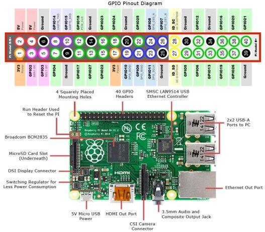
In this example, I will use the Raspberry Pi SPI0 to connect the CC1101. The SPI0 pins are 19, 21, 23 and 24. Also I will implement the pin 17 for voltage and 20 for ground. Adding the pin 22 for the digital output CC1101’s GD02.
CC1101 pinout:
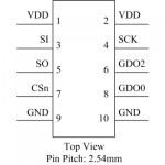
Connecting the CC1101 and Raspberry Pi SPI.
CC1101<->Raspi

Vdd    -    3.3V (P1-17)
SI     -    MOSI (P1-19)
SO     -    MISO (P1-21)
CS     -    SS   (P1-24)
SCLK   -    SCK  (P1-23)
GDO2   -    GPIO (P1-22)
GDO0   -    not used in this demo
GND    -    P1-20
One of the main wiring problems is the necessity to implement many cables to connect the Raspberry Pi and the CC1101 which could be a mess:
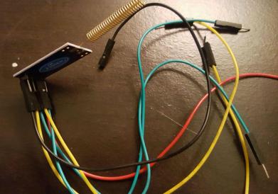
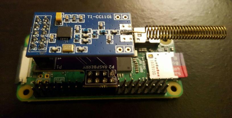
I started designing a prototype to connect both devices easily. As result, we have a PCB that could be a perfect device to plug and play:
The software
First, we need to enable the Raspberry Pi SPI:
pi@raspberrypi:~/CC1101 $ sudo raspi-config
In order to add functionality to the CC1101 and Raspberry Pi, we have to implement a special library: https://github.com/SpaceTeddy/CC1101(Thanks for this amazing code) follow the instructions in the README.md to compile & run the receiver and transmitter.
At the end, we are able to implement the hardware and software very easily:
I forked the original library and added the PCB schematic: https://github.com/salmg/CC1101/tree/master/schematic
Testing both Raspberry Pis TX/RX pic.twitter.com/YyNzdRI3OW
— Salvador Mendoza🇲🇽 (@Netxing) October 3, 2017
Thanks @Sabasacustico

Great project! Thanks for sharing
LikeLike
Big thk’s for sharing !
It works for me for the TX module (I can see pic on my oscilloscope) but I don’t receive anything on RX (no values change).
Any idea pls ?
LikeLike
Take a look at the issues section in its repository: https://github.com/SpaceTeddy/CC1101/issues/11
LikeLike
Thk’s for your fast reply 🙂
No more issue for the moment and the same in 433. 😦
I use the same module to Tx & Rx. Could it be my problem ?
I use a VT-CC1101-868MWirelessModule or another one in 433Mhz (the same has yours, 3.3v), Pi 3.
My result with the 868 module:
pi@raspberrypi:~/868/CC1101-master $ sudo ./TX_Demo -v -a1 -r3 -i1000 -t5 -c1 -f868 -m100
CC1100 SW: Verbose option is set `’
Raspberry CC1101 SPI Library test
Init CC1100…
Partnumber: 0x00
Version : 0x14
…done!
Mode: 3
Frequency: 3
Channel: 1
My_Addr: 1
Config Register:
0x07 0x2E 0x80 0x07 0x57 0x43 0x3E 0x0E 0x45 0x01
0x01 0x08 0x00 0x21 0x65 0x6A 0x5B 0xF8 0x13 0xA0
0xF8 0x47 0x07 0x0C 0x18 0x1D 0x1C 0xC7 0x00 0xB2
0x02 0x26 0x09 0xB6 0x04 0xEB 0x0B 0x3C 0x11 0x41
0x00 0x59 0x7F 0x3C 0x81 0x3F 0x0B
PaTable:
0x03 0x17 0x1D 0x26 0x50 0x86 0xCD 0xC0
TX_FIFO: 0x06 0x03 0x01 0x00 0x00 0x03 0xE8
#:0x01
TX_FIFO: 0x06 0x03 0x01 0x00 0x00 0x03 0xE8
#:0x02
TX_FIFO: 0x06 0x03 0x01 0x00 0x00 0x03 0xE8
#:0x03
& in another terminal on the same Pi, at the same time:
~/868/CC1101-master $ sudo ./RX_Demo -v -a3 -c1 -f868 -m100
CC1100 SW: Verbose option is set `’
Raspberry CC1101 SPI Library test
Init CC1100…
Partnumber: 0x00
Version : 0x14
…done!
Mode: 3
Frequency: 3
Channel: 1
My_Addr: 3
Config Register:
0x07 0x2E 0x80 0x07 0x57 0x43 0x3E 0x0E 0x45 0x03
0x01 0x08 0x00 0x21 0x65 0x6A 0x5B 0xF8 0x13 0xA0
0xF8 0x47 0x07 0x0C 0x18 0x1D 0x1C 0xC7 0x00 0xB2
0x02 0x26 0x09 0xB6 0x04 0xEC 0x0B 0x3D 0x11 0x51
0x00 0x59 0x7F 0x3C 0x81 0x3F 0x0B
PaTable:
0x03 0x17 0x1D 0x26 0x50 0x86 0xCD 0xC0
… and no refresh
flashman21 said:
“Only one thing I changed was register parameters in cc1100_raspi.cpp (cc1100_GFSK_1_2_kb) to be the same as mine TX module.
But this should not affect init comunication.”
My module is:
Central frequency is 868MHz, Frequency bands :779~928MHz
Programmable output power up to +10dBm for all supported
frequencies,the communication distance is above 200m in sight .
High receiver sensitivity down to -110dBm(at 2.4Kbps data rate)
Programmable baseband modulator with GFSK/2-FSK/ASK/OOK/MSK
Programmable data rate 1.2~500Kbps
64-byte TX data FIFO
…so witch parameter must I have to select ?
One time i have got ACK when I was plugin LED on MOSI and MISO Pin on the Breadboard (never append another time):
RX_FIFO:0x1F 0x1F 0x1F 0x1F 0x1F 0x1F 0x1F 0x1F 0x1F 0x1F 0x1F
0x1F 0x1F 0x1F 0x1F 0x1F 0x1F 0x1F 0x1F 0x1F 0x1F 0x1F 0x1F 0x1F
0x1F 0x1F 0x1F 0x1F 0x1F 0x1F 0x1F 0x00 | 0x00 0x00 |
RSSI:-78 LQI:0x00 CRC:0x00
TX_FIFO: 0x05 0x1F 0x1F 0x41 0x63 0x6B
Ack_sent!
RX_FIFO:0x16 0x0E 0x3B 0xEE 0xD0 0x77 0xCE 0x1F 0x1F 0x1F 0x1F
0x1F 0x1F 0x1F 0x1F 0x1F 0x1F 0x1F 0x1F 0x1F 0x1F 0x1F 0x1F |
0x1F 0x1F |
RSSI:-63 LQI:0x1F CRC:0x00
TX_FIFO: 0x05 0x3B 0x0E 0x41 0x63 0x6B
Thk’s again and “bravo” for your website !
Nels
LikeLike
… and something very strange. This morning i have launch the Rx & Tx prog. in two terminal and nothing received … except when I switch OFF / ON the VCC on the module.
After a reboot I have try again the same process but no ACK 😦
thk’s for reading
LikeLike