Card Relay Internals
How a physical smart card connected to a desk-side reader can be made to communicate with a remote terminal as if the card were connected locally. The research focuses on ISO/IEC 7816-3 T=1, including ATR handling, protocol negotiation, block framing, sequencing, and APDU relaying.
Introduction
SIMtrace2 T1 Research extends Osmocom’s SIMtrace2 card emulation with an ISO 7816-3 T=1 block layer. Upstream cardem supports T=0; this version supports both protocols and selects the terminal-side protocol from the ATR, with PPS available for negotiation.
SIMtrace2 was originally designed for SIM-card communication, with T=0 as the primary protocol. Supporting payment cards introduces additional requirements. EMV cards can use T=0 or T=1, require protocol negotiation, and may enforce stricter timing and communication behavior. These differences make reliable card emulation and relaying more challenging. Many use T=1, the block-oriented protocol, and their ATR advertises timing and block parameters that the terminal expects the interface to honor. On top of ISO 7816-3, the terminal also applies EMV-specific constraints, so an incompatible ATR can be rejected before the first APDU is exchanged.
The original relay did not work when placed between an EMV card and a payment terminal. The failure was not a single bug; several independent issues appeared in sequence, with each one masking the next.
| At the outset | Now | |
|---|---|---|
| Protocol to the terminal | T=0 only | T=0 or T=1, selected from the ATR and renegotiable by PPS |
| Protocol to the real card | T=0 only over PC/SC, so a T=1-only card could not be relayed at all | Both offered; reader and card negotiate. –card-proto pins it |
| ATR | A hardcoded 3B 00, so the terminal saw a generic card and never this one | The real card’s, rewritten to keep its identity and protocol parameters while dropping the timing promises the board cannot keep |
| PPS | Proposals echoed back unchecked, behind a FIXME about validating them against the ATR | Validated against what the ATR actually offered. Otherwise the card stays mute, as ISO 7816-3 §9.3 requires |
| EMV proprietary class 0x80 | Classified as case 0, logged as an error, and dropped, so the transaction stalled at GET PROCESSING OPTIONS | Classified directly, with P3 read as Lc and GENERATE AC decoded from P1 |
| Case-4 APDUs across a protocol mismatch | Not handled | Converted, so a T=1 card can be presented to a T=0 reader |
| Re-use after a transaction | The board had to be reset by hand before it would work again | –auto-reinit replays removal, insertion, and reset so the terminal starts a fresh session |
| Firmware base | An earlier 0.7.0 fork, which on this hardware never produced an ATR at all | Upstream 0.9.1-22-*, with the T=1 block layer applied on top |
What that adds up to
The result is a complete EMV transaction between a physical card in a desk-side reader and a payment terminal: application selection, processing options, record reads, and both GENERATE AC exchanges, ending in a card decision. The card first requests online authorization; with no acquirer available in the test setup, the transaction ultimately declines. This matches the behavior observed when the same card is inserted directly into the terminal.
This has now been demonstrated through both terminal-facing configurations. In the native case, the board speaks T=1 to the terminal and presents the card’s rewritten ATR. In the second case, –synthetic-atr presents a T=0 face to a Verifone terminal while the real card remains on T=1 behind the relay. Section 09 contains both traces; section 04 explains why the second configuration is required for that terminal.
The T=1 implementation is a self-contained block layer covering LRC and CRC framing, I-, R-, and S-blocks, sequence numbering, bidirectional chaining, IFS negotiation, and RESYNCH, ABORT, and WTX handling. It depends only on <string.h> and its own header. That isolation allowed it to survive a firmware rebase onto upstream without modification and makes the block layer straightforward to exercise on a workstation without the board.
The character of the work
Three defects separated successful activation from a completed transaction, and they shared an important characteristic: none produced a useful error message. The terminal rejected an ATR even though every byte was transmitted correctly. Responses were freed inside the firmware without a log. Chained responses collided on the wire while the host logs still looked healthy. The failures were isolated by reasoning from the expected wire behavior and by using a direct-card control experiment to determine whether the terminal or the relay was responsible.
A fourth issue was easier to spot but still prevented the transaction from working: EMV proprietary commands were classified as unknown, logged, and dropped. This issue is discussed in Section 05.
The sections that follow trace the implementation from activation through the ATR rewrite, protocol selection, EMV APDU handling, T=1 block transport, and complete transaction traces. The final section records what remains unverified on hardware. The goal is to make the boundary between demonstrated behavior and remaining work explicit.
What the relay does and what is proven
A real card is connected to a PC/SC reader on a Linux host. simtrace2-remsim communicates with the reader over PC/SC and forwards APDUs to a SIMtrace2 board. The board presents itself to the EMV terminal at the electrical interface: VCC, clock, reset, and a single half-duplex I/O line.
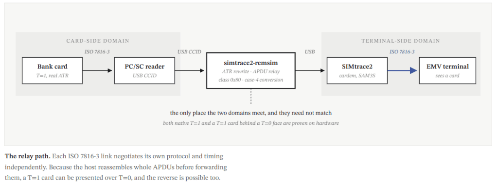
Do the two sides of the relay really need to speak the same protocol?
The key observation is that they do not. The card can communicate using T=1, while the relay presents T=0 to the terminal. Because the relay operates on complete APDUs rather than transparently forwarding protocol characters, each side can remain in its own independent protocol domain. The relay effectively decouples the two protocol domains by terminating one transport protocol, reconstructing the APDU, and issuing the corresponding transaction on the other side.
Both configurations have now carried a complete EMV transaction on hardware. The status board below distinguishes hardware evidence from unit-test coverage; that distinction is maintained throughout the document.
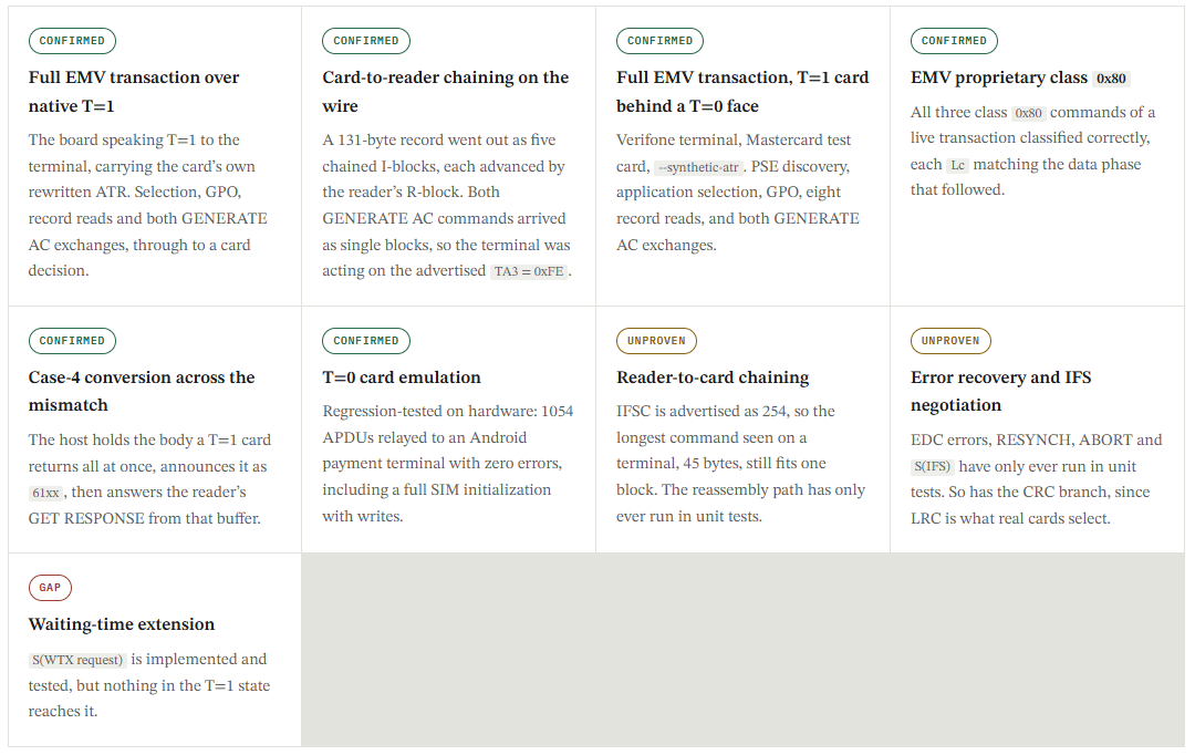
Which face to present is a property of the terminal, not of the card. Native T=1 is the direct path and it works. A terminal that refuses an ATR naming T=15, as the Verifone in section 04 does, is served instead by a T=0 face with the host converting case 4 on the way through. Both reach a card decision. Keep the two straight when reading a log, because the firmware state and the host code path differ completely between them.
Activation: from VCC to a chosen protocol
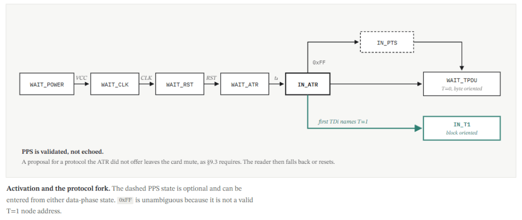
The terminal drives the electrical activation sequence, and the board responds to each transition through SAM3S interrupts. Card emulation is implemented as a state machine rather than a polling loop.
The key decision occurs after the ATR is transmitted. The firmware evaluates the ATR’s TDi chain to determine the protocol it has advertised, then enters either the byte-oriented T=0 path or the block-oriented T=1 path.
Upstream went straight to ISO_S_WAIT_TPDU here, because T=0 was the only option. This tree replaces that with enter_data_phase() and data_phase_state(), which read atr_proto_mask and pick the matching state.
The PPS check upstream left open
Upstream copied the reader’s proposal into the response and marked the spot with a FIXME reading check if proposal matches capabilities in ATR. A reader could therefore propose T=1 to a firmware that only spoke T=0 and be told yes.
The check is now in place. A proposal is accepted only if the protocol appears in both SUPPORTED_PROTOCOLS and the mask the ATR actually announced. Otherwise the firmware logs the proposal, stays silent, and returns to waiting for a fresh PPS, which is the behavior ISO 7816-3 §9.3 prescribes.
The ATR is rewritten before it is pushed
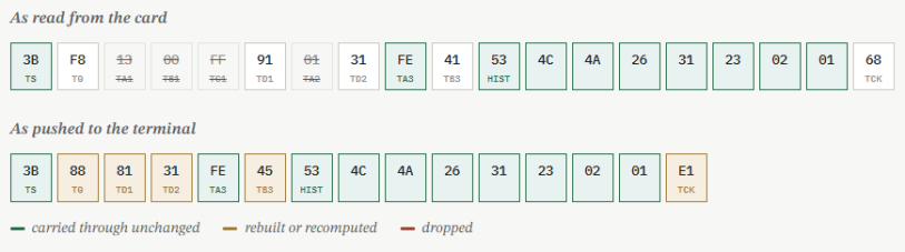
The card’s ATR is read over PC/SC and forwarded after rewriting rather than copied verbatim. The emulation operates with one set of transmission parameters, based on the ISO defaults and changed only by a successful PPS exchange. Interface bytes that request timing the board cannot provide therefore cannot be forwarded unchanged.
Forwarding TA1 can cause the reader to select a clock rate the board cannot sustain. Forwarding TA2 can apply that mode immediately, without giving PPS an opportunity to reject it. In either case, the terminal observes framing errors rather than a usable card interface.
Dropped
| Byte | Promises | Firmware |
|---|---|---|
| TA1 | Fi/Di. 0x96 asks for 16 clocks per etu, not 372 | ignores it |
| TB1 | deprecated programming voltage | ignores it |
| TC1 | extra guard time between characters | ignores it |
| TA2 | specific mode: adopt TA1 at once, no PPS | ignores it |
Kept, and why it matters
TA3 and TB3 look like more of the same and are not. They are protocol parameters rather than electrical ones. TA3 is the IFSC and TB3 is the BWI/CWI pair.
EMV Book 1 §8.3 requires TB3 and rejects the card unless BWI ≤ 4 and CWI ≤ 5. With TB3 absent the terminal falls back to the ISO default CWI = 13, which is out of range, so it refuses the card before a single block is exchanged. Nothing looks wrong at the character level. The ATR is simply turned down.
The global bytes carried behind a TDi naming T=15 are kept for the same reason: they are not electrical promises either. TA carries the clock-stop indicator and the supply voltage classes the card accepts, and TB carries power consumption. A modem running its SIM interface at 1.8 V has no reason to accept a card that never declares it tolerates 1.8 V.
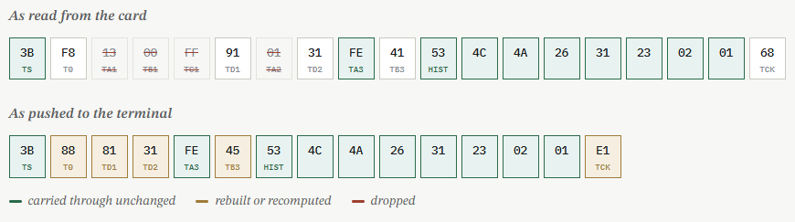
Nineteen bytes in, fifteen out. The historical bytes survive untouched, so the terminal still sees the real card’s identity. TD1 becomes 0x81 and TD2 becomes 0x31 because TA3 and TB3 are protocol-specific only from the third interface-byte group on. The T=1 link has to be TD2 or later, which is exactly why real T=1 cards name T=1 twice. TB3 is emitted as 0x45, meaning BWI 4 and CWI 5, the most generous pair EMV accepts, since the relay adds a USB and PC/SC round trip to every exchange. TCK is recomputed over the new body. This card never names T=15, so the global-byte path below does not apply to it.
The T=15 conflict, and why EMV needs a synthetic ATR
A SIM ATR can name T=15 in its TDi chain. T=15 is not a transmission protocol; it identifies subsequent interface bytes as global parameters, including clock-stop behavior and supported supply-voltage classes. The rewriter preserves those parameters and emits them behind a rebuilt TDi chain where appropriate.
For the terminal configuration described here, EMV Book 1 §8.3 permits T=0 and T=1. A terminal that encounters T=15 in the TDi chain may therefore reject the card before any APDU exchange begins.
This creates a practical incompatibility between the SIM-side requirements and this terminal. There is no single ATR representation that satisfies both environments. –synthetic-atr therefore presents 3B 00, with no interface bytes, when the terminal requires a minimal EMV-compatible ATR.
Measured against a Verifone terminal, in order
| ATR presented | Reached VCC and CLK with reset released | APDUs |
|---|---|---|
| rewritten, T=15 kept, TA3 dropped | never | 0 |
| –raw-atr, TA1 = 0x96 forwarded | yes, cycling | 0 |
| rewritten, T=15 kept, TA3 kept | yes, consistently | 0 |
| –synthetic-atr, 3B 00 | yes | all of them |
Read that ladder carefully, because it says two things. Keeping TA3 and TB3 is what got the terminal to hold the card powered and released instead of deactivating it, so that fix is real. On this particular terminal it was still not sufficient: as long as the chain named T=15, it exchanged nothing, and only 3B 00 produced a transaction.
The ladder is a property of this terminal, not of the rewrite. Against a terminal that accepts the rewritten ATR, those same bytes carry native T=1 end to end, which is the first trace in section 09. The difference is entirely T=15, and a card whose ATR never names it is unaffected either way.
–raw-atr fails for the original reason the rewriter exists. TA1 = 0x96 asks for 16 clock cycles per etu while the emulation runs a fixed 372, so every byte is framed wrong.
EMV support over T=0 and T=1
The previous sections focused on getting the interface onto the wire. This section moves up one layer to the host, where complete APDUs are interpreted and relayed. Two issues are critical here; without either fix, the EMV transaction cannot complete regardless of the transport protocol.
The first is handling EMV’s proprietary command class. The second is translating between T=0 and T=1 when the card and terminal use different protocols.
The proprietary class 0x80
Upstream classifies each command APDU with osim_determine_apdu_case(), which matches it against the UICC/SIM class table. Every EMV proprietary CLA = 0x80 command matches nothing there and comes back as case 0. Case 0 is not an ISO 7816-4 case at all. It is the table’s way of saying it does not recognize the command.
The dispatcher treats that as an error, logs Unknown APDU case 0, and returns -1. The APDU is dropped and the exchange stalls. Three of the commands in a routine EMV transaction are class 0x80, and the first of them is GET PROCESSING OPTIONS, so that is where every transaction stopped.
host/lib/apdu_dispatch.c adds a case 0 arm that classifies these directly.
| Command | P3 | |
|---|---|---|
| 80 A8 00 00 02 83 00 | GET PROCESSING OPTIONS | Lc |
| 80 CA 9F 36 05 | GET DATA (ATC) | Lc |
| 80 AE 80 00 1D | GENERATE AC, ARQC | Lc |
| 80 AE 90 00 2B | GENERATE AC, ARQC with CDA | Lc |
GENERATE AC encodes the requested cryptogram in P1. Bits 7 and 6 select AAC, TC or ARQC, and bit 4 adds CDA. The four values that carry command data are 0x40, 0x50, 0x80 and 0x90, and they take P3 as Lc. Any other non-zero P1 on class 0x80 has neither command data nor expected data. When P1 is zero, P3 is Lc, which covers GET PROCESSING OPTIONS and GET DATA above. Command data is then accumulated across USB messages exactly as ISO cases 3 and 4 do.
What a live terminal produced
| Command | P1 | Branch | Lc |
|---|---|---|---|
| 80 A8 00 00 02 GET PROCESSING OPTIONS | 0x00 | else | 2 |
| 80 AE 90 00 2B GENERATE AC, ARQC with CDA | 0x90 | cryptogram | 43 |
| 80 AE 00 00 1D GENERATE AC, AAC | 0x00 | else | 29 |
Each classification was correct, and each Lc matched the data phase that followed. Verified against a Verifone terminal and a Mastercard test card.
The same transaction over two different faces
The protocol toward the terminal and the protocol toward the card are set independently, so the host has to reconcile them. There are two arrangements that matter in practice.
| Face to terminal | Card | What the host does |
|---|---|---|
| T=0 proven | T=0 or T=1 | Reassembles TPDU fragments into a command APDU using procedure bytes, sends it over PC/SC, then feeds the response back as procedure bytes and a status word. When the card is T=1, the response arrives whole, so case 4 needs the conversion described below. |
| T=1 proven | T=0 or T=1 | Receives the INF of each I-block, appends it to a reassembly buffer, and forwards the command once CEMU_DATA_F_FINAL arrives. The response goes back in 32-byte chunks with the status word attached. No procedure bytes are involved in either direction. |
Case 4 across the mismatch
A case-4 command carries data to the card and expects data in return. Under T=0, the reader expects the status word first and then issues GET RESPONSE for the response body. A T=1 card has no procedure-byte exchange; the response body is returned as part of the complete APDU that PC/SC provides to the host.
So when the reader asked for no data but the card returned some, the host holds the body in a buffer and answers 61 xx with the length, exactly as a T=0 card would. The reader then issues GET RESPONSE, and the host serves it from that buffer rather than forwarding it to the card, which has nothing left to give. If more remains it announces another 61 xx, otherwise 90 00. Any other command supersedes whatever was still held.
The trap in the other direction. PC/SC readers commonly do not perform the case-4 to GET RESPONSE conversion for you. A case-4 APDU with an explicit Le can still return 61 xx with no body. Under T=0 relaying this is invisible, because the reader issues its own GET RESPONSE and you relay it. Under T=1 whole APDUs are exchanged and there is no such round trip, so a host must run the 61 and 6C loop against the card itself or lose every response body.
Selecting the protocol toward the card
host/lib/reader_pcsc.c is a PC/SC backend that supports both protocols and takes an explicit mask, so the reader and card negotiate whichever they can agree on. -T or –card-proto pins it to t0, t1 or auto, and auto is the default. This setting has no bearing on what is presented to the terminal.
The T=1 block layer
card_emu_t1.c is self-contained. It includes <string.h> and its own header, nothing else. It has no hardware or USB dependency, which is why it survived a firmware rebase onto upstream 0.9.1-22-* without a single edit, and why it can be unit-tested on a workstation.
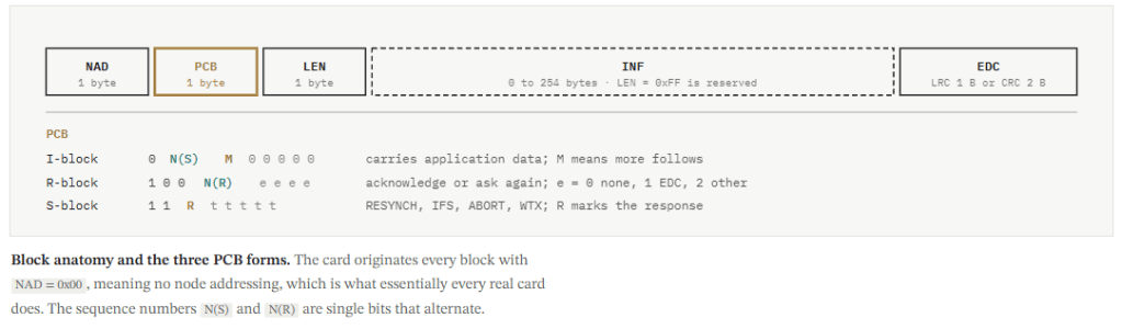
Every block has the same five fields. Only the PCB changes what the block means.
What is implemented, and how far it has been exercised
There are 14 unit tests in firmware/test/card_emu_t1_tests.c, one for each capability below, and they run on a workstation with no board attached. The third column says how far each has been pushed beyond that: on hardware means a real reader drove it during the native T=1 transaction in section 09.
| Capability | Covered by | State |
|---|---|---|
| Block framing, LRC and CRC-16/CCITT-FALSE | test_lrc, test_crc_len, test_crc_roundtrip | tested |
| I / R / S blocks, sequence numbering | test_simple_exchange | on hardware |
| Card to reader chaining | test_chained_response | on hardware |
| Reader to card chaining | test_chained_command | unit tests only |
| R-blocks: EDC error, sequence error, retransmit | test_edc_error, test_sequence_error, test_retransmit | unit tests only |
| IFS negotiation | test_ifs_negotiation | unit tests only |
| RESYNCH and ABORT | test_resynch_and_abort | unit tests only |
| Bounds: reserved LEN=FF, 254-byte INF | test_reserved_len, test_max_size_block | tested |
| WTX request | test_wtx | unreachable |
The last row is not a coverage gap. t1_tx_wtx_request() works and its test passes, but nothing in the firmware calls it. Section 12 explains why.
Turn-taking on a shared wire
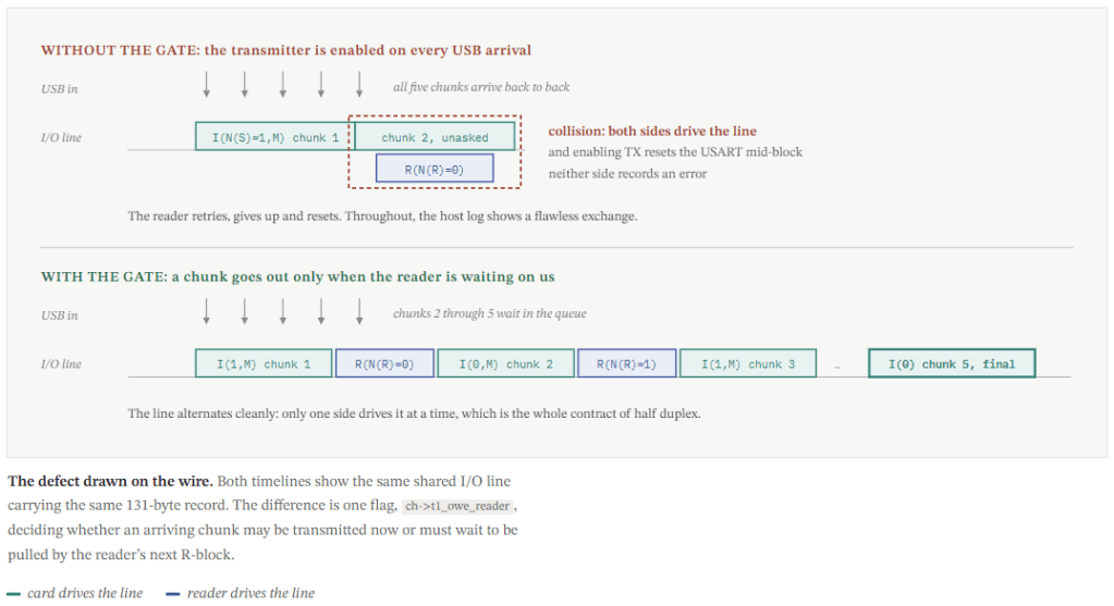
This is where the relay differs most from a conventional card. A real card generates its response locally and transmits it. Here, the response arrives from the host over USB and may already be divided into several chunks before the firmware transmits it.
A response longer than IFSD must be chained: the card sends an I-block with the more bit set, waits for the reader’s R-block, and then sends the next block. The host does not manage that turn-taking; it provides the complete response, while the firmware is responsible for sequencing the blocks on the wire.
In the observed transaction, a 131-byte record becomes five blocks. Because the card and reader share a single half-duplex I/O line, the firmware must never begin transmitting while the reader is still driving the line.
The gate, in code
The T=0 arm of the same switch had always been conditional. The T=1 arm was not, and a T=1 response is the only kind that arrives as several messages.
/* card_emu_have_new_uart_tx() */
case ISO_S_IN_TPDU:
    switch (ch->tpdu.state) {
    case TPDU_S_WAIT_TX:
    case TPDU_S_WAIT_PB:   // only when we owe data
        card_emu_uart_enable(ch->uart_chan, ENABLE_TX);
    ...

case ISO_S_IN_T1:
-   card_emu_uart_enable(ch->uart_chan, ENABLE_TX);
+   if (ch->t1_owe_reader && !t1_tx_pending(&ch->t1))
+       card_emu_uart_enable(ch->uart_chan, ENABLE_TX);
    break;
The flag is set when a complete command goes to the host, and again when an R-block asks for the next chunk. It is cleared the moment a chunk is taken off the queue. Because tx_byte_t1() consults it too, a chunk cannot reach the line out of turn whichever path runs. And if the R-block arrives before the host has delivered the chunk it asks for, that chunk goes out the instant it lands rather than stalling.
How this is held in place. The fix is what let the 131-byte record in section 09 go out as five chained blocks against a real reader. It is kept honest by test_t1_response_chunks_arrive_together(), which queues an entire response up front and asserts that the card stays silent after the first block until the R-block arrives. That test exists because the original harness could not have caught this, for reasons in section 10.
The USB message plane
The host and firmware exchange framed messages over bulk endpoints, with an interrupt endpoint carrying status information. A small set of message types carries the relay traffic, while flags determine how each payload should be interpreted.
| Message | Direction | Carries |
|---|---|---|
| DO_CEMU_RX_DATA | firmware to host | Bytes received from the reader. For T=1, the INF of one I-block. |
| DT_CEMU_TX_DATA | host to firmware | A response to transmit. For T=1, one chunk, which becomes exactly one I-block. |
| DT_CEMU_SET_ATR | host to firmware | The rewritten ATR, installed before activation. |
| DT_CEMU_CARDINSERT | host to firmware | Card presence, which –auto-reinit toggles to start a fresh session. |
| BD_CEMU_STATUS | firmware to host | VCC, CLK, RST, Fi/Di and waiting time. Batched on the interrupt endpoint. |
Flags on a data message
| Flag | Value | Meaning |
|---|---|---|
| CEMU_DATA_F_TPDU_HDR | 0x01 | T=0: payload is a five-byte TPDU header |
| CEMU_DATA_F_FINAL | 0x02 | last piece. For T=1 it clears the chaining bit |
| CEMU_DATA_F_PB_AND_TX | 0x04 | T=0: procedure byte, then the card transmits |
| CEMU_DATA_F_PB_AND_RX | 0x08 | T=0: procedure byte, then the card receives |
| CEMU_DATA_F_T1_BLOCK | 0x10 | T=1: payload is block INF, not a TPDU fragment |
The T=1 contract, if you write your own host
The firmware owns EDC, sequence numbers, R-blocks and S-blocks. The host supplies and consumes INF only, never raw blocks. NAD, PCB, LEN and the EDC never cross USB. Three details are easy to get wrong.
| Rule | Why |
|---|---|
| Chunk responses at 32 bytes | T1_HOST_CHUNK is 32 because T1_DEFAULT_IFS is 32, and t1_tx_inf() rejects anything larger. The firmware logs the rejection and drops the chunk, so an oversized write is silently lost. The negotiated IFSD is never reported back over USB, so 32 is the only value a host can safely assume even after a successful S(IFS) exchange. Push all chunks back to back; the firmware releases them one per reader acknowledgement and there is no per-chunk ack to wait for. |
| Do not strip the status word | Under T=0 the host splits SW1SW2 off the response. Under T=1 it must not. The status word is the tail of the response APDU and the reader’s own T=1 stack consumes it. |
| A non-final block gets no reply | When CEMU_DATA_F_FINAL is clear, append to the reassembly buffer and return without sending anything. The firmware answers a chained I-block itself with an R-block. |
The gate that silently ate every response. dispatch_usb_command_cardem() drops a TX_DATA message when card_emu_ch_ready() says the channel is not ready. It calls usb_buf_free(msg) with no log and no error to the host. That helper enumerated the T=0 data-phase states and predated T=1, so ISO_S_IN_T1 fell through to its default: and every T=1 response was discarded inside the firmware. The host had sent it, the card fell silent, and the reader waited out BWT and reset. ISO_S_IN_T1 is now in the ready list, with a comment saying why.
Two transactions, as they actually ran
Both runs reached a card decision. The key difference is the protocol and ATR presented to the terminal. Reading the commands in sequence exposes the decisions made by the EMV kernel as the transaction progresses.
Sensitive card data is intentionally omitted. Primary account numbers, Track 2 data, and the cardholder name are redacted from the traces below.
Run one: native T=1, the card’s rewritten ATR
The board negotiated T=1 with the terminal and the block layer carried every exchange. This is the trace the capability table in section 06 refers to when it says on hardware.
→ 00 a4 04 00 0e 31 50 41 59 2e 53 59 53 2e 44 44 46 30 31 00   SELECT 1PAY.SYS.DDF01
← 6f 1a 84 0e ... a5 08 88 01 01 5f 2d 02 65 6e 90 00           FCI, directory is at SFI 1

→ 00 b2 01 0c 00                                                READ RECORD 1, SFI 1
← 70 1b 61 19 4f 07 a0 00 00 00 03 10 10 50 0b ... 90 00        AID a0000000031010, VISA CREDIT

→ 00 b2 02 0c 00                                                READ RECORD 2, SFI 1
← 6a 83                                                         end of directory, expected

→ 00 a4 04 00 07 a0 00 00 00 03 10 10 00                        SELECT the AID
← 6f 20 84 07 ... 87 01 01 90 00                                36 B, chained over 2 blocks

→ 80 a8 00 00 02 83 00 00                                      GET PROCESSING OPTIONS   [CLA 0x80]
← 80 06 18 00 08 02 03 00 90 00                                AIP 1800, AFL 08 02 03 00
                                                               SFI 1, records 2 to 3, 0 for offline auth

→ 00 b2 02 0c 00                                              READ RECORD 2
← 70 23 57 13 ... 5f 20 0b ... 90 00                          track 2 and name, 2 blocks

→ 00 b2 03 0c 00                                              READ RECORD 3
← 70 7f 5a 08 ... 8c 15 ... 8d 19 ... 96 90 00                131 B, chained over 5 blocks
                                                              CDOL1 (8c) asks for 29 bytes

→ 80 ae 80 00 1d 00 00 00 00 05 ... 43 00                     GENERATE AC, P1=80, 35 B, one block
← 80 12 80 00 1a ed 4a 80 8f ... 90 00                        CID 0x80 = ARQC: go online

→ 80 ae 00 00 27 5a 33 00 00 00 00 05 ... 00 00 00            GENERATE AC, P1=00, 45 B, one block
← 80 12 00 00 1a 5c bf 7f 7c ... 90 00                        CID 0x00 = AAC: declined
The decline is the expected outcome. The card returned a genuine ARQC asking for online authorization. With no acquirer to reach, the terminal issued a second GENERATE AC requesting an AAC and the card declined. That is precisely what the same card does inserted directly into the same terminal. Reaching a decision is the success condition, not the decision itself.
Two details in that trace are worth pulling out. The 131-byte record went out as five chained I-blocks, each one released by the reader’s R-block, which is the turn-taking of section 07 working on a real wire. And both GENERATE AC commands, 35 and 45 bytes, arrived as single blocks, which proves the terminal was acting on the TA3 = 0xFE IFSC the rewritten ATR advertises. For the same reason, reader-to-card chaining stayed unexercised: ordinary EMV commands never need it.
Run two: T=0 face, Verifone terminal
A Verifone terminal will not accept an ATR whose TDi chain names T=15, and section 04 has the ladder that establishes it. Relaying to that terminal means –synthetic-atr, so the board presents T=0 while the card behind it stays on T=1 and the host converts between them. Mastercard test card.
→ SELECT 1PAY.SYS.DDF01                    ← 61 20, then FCI on GET RESPONSE
→ READ RECORD, PSE directory              ← six Mastercard applications
→ SELECT a0000000041010                   ← 61 3E, then FCI on GET RESPONSE

→ 80 A8 GET PROCESSING OPTIONS           ← AIP + AFL            [CLA 0x80]
→ READ RECORD × 8 across the AFL        ← PAN, track 2, CVM list, certificates

→ 80 AE GENERATE AC, P1 = 0x90           ← 9F27 = 80, ARQC with CDA   [CLA 0x80]
→ 80 AE GENERATE AC, P1 = 0x00           ← 9F27 = 00, AAC, declined     [CLA 0x80]
What the two runs prove between them
The block layer works on a real wire. Run one is the T=1 face end to end: activation, protocol selection from the ATR, I-blocks and R-blocks, sequence numbering, and card-to-reader chaining across a five-block response.
The class 0x80 arm is load-bearing in both. Every 80 xx command in either trace returns case 0 from osim_determine_apdu_case(). Without the case 0 arm, upstream logs an error and drops them, and the transaction stops at GET PROCESSING OPTIONS. On the Verifone run each classification was correct with Lc matching the data phase that followed: 2, 43 and 29 bytes.
The case-4 conversion is what makes run two possible. Both 61 20 and 61 3E are synthesized by the host, not by the card. The card is on T=1 and handed the FCI over in one piece; the terminal is on T=0 and expects a status word first, so the host held the body, announced its length, and served the reader’s GET RESPONSE from that buffer. Run one needs none of that, because whole APDUs cross the wire in both directions.
The same two problems, met independently
The SIM-side Python tool this firmware was developed alongside relays EMV as well, and hit both problems on its own. It reached the same conclusion on the ATR, sending 3B 00. On class 0x80 it took a different shape: rather than a generic case 0 arm with a P1 test, it keys on the instruction, 0xA8 for GET PROCESSING OPTIONS and 0xAE for GENERATE AC, both of which carry command data unconditionally. That is only possible because it consults a SIM instruction table first, so the class 0x80 commands a SIM defines (STATUS, FETCH, TERMINAL PROFILE, TERMINAL RESPONSE) are classified before the EMV rule is ever reached. Both arrive at the same behavior for the three commands measured here. The C version classifies more broadly and needs the P1 test to do it; the Python version classifies narrowly and does not.
Full report: here
Github: https://github.com/salmg/SIMtrace2-T1-Research

