
Idea
How to add new tracks or send some data to the MagSpoof remotely? Without recompile it and using the same hardware for the communication process. This project could be useful to send data by Internet which could be retransmitted to the MagSpoof receiver automatically using a simple ESP32, for example.
Intro
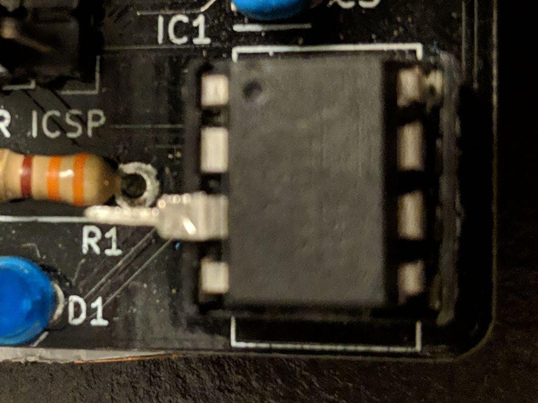
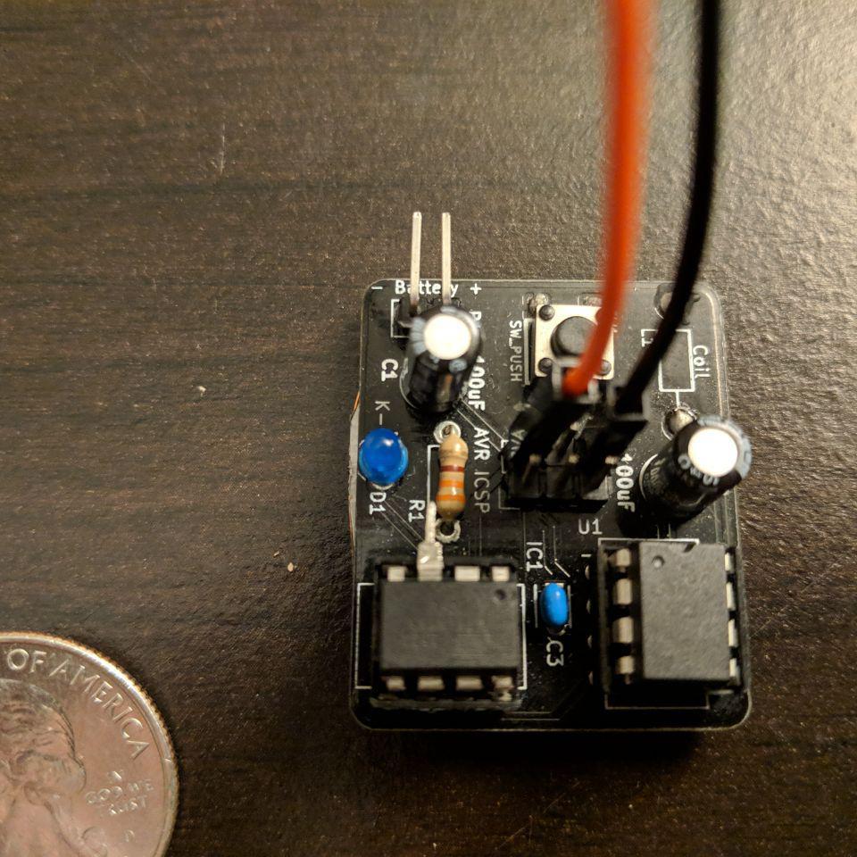
MagSpoof is an excellent tool by itself. Thanks to Samy Kamkar, the tool is very portable and easy to use. There are different versions in the market. Specifically for this post, I will use the Electronic Cats version.
The MagSpoof implements 6 ATTiny85 pins(counting VCC and GND):

The only unused pin in the MagSpoof project is the number 4. To have a better understanding of the ATTiny85 pins, we need to take a look at the ATTiny85 pinout:
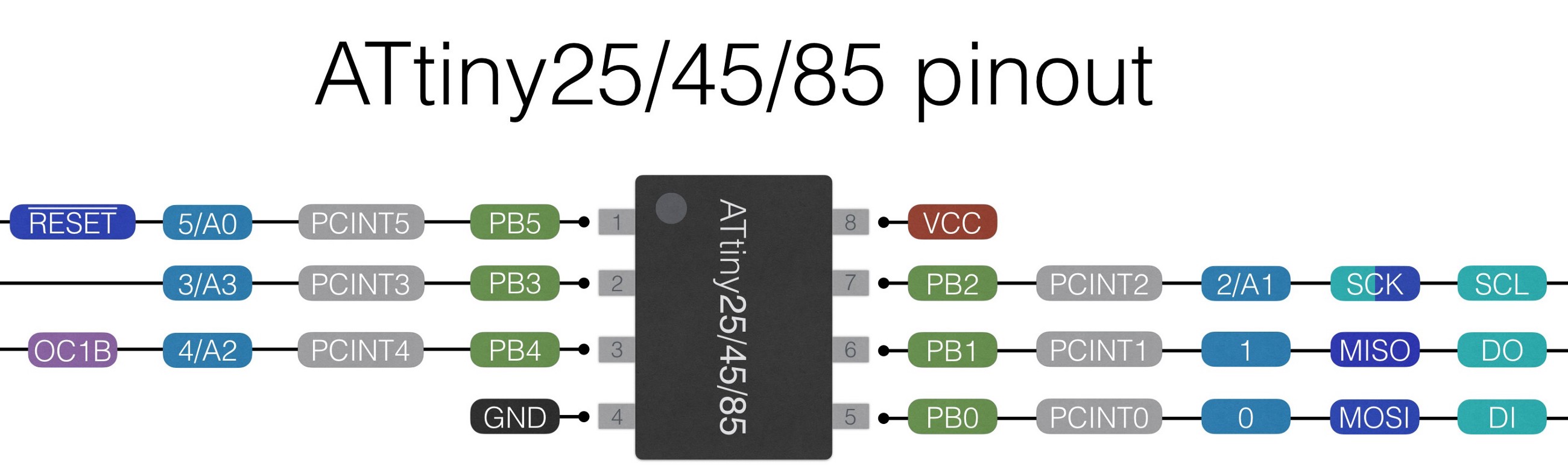
Be aware that the physical pin numbers differ from digital/analog number pins. For example, the unused digital pin 4(blue 4/A2 in the picture) in the MagSpoof; it is the physical 3(gray 3 in the picture)
To be clear, when I refer to the pin 4, I will talk about the blue digital 4 in the picture.
Hardware
Adding SDR support to MagSpoof with only one pin seems complicated. Initially, the MagSpoof was designed to run with a 3.7V LiPo battery. So I needed to find a radio with that characteristics in specific to avoid the idea of add new hardware; which could make things more complex.
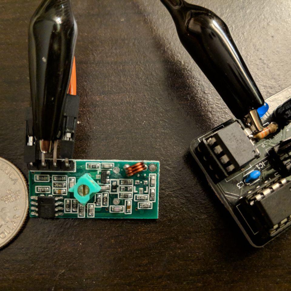
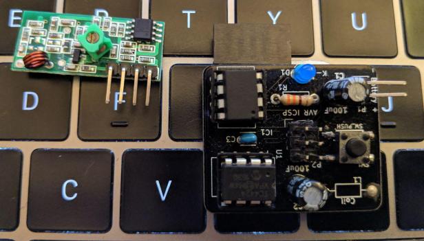
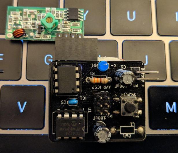
I found this version of 315MHz radios:
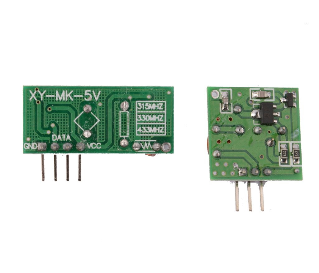
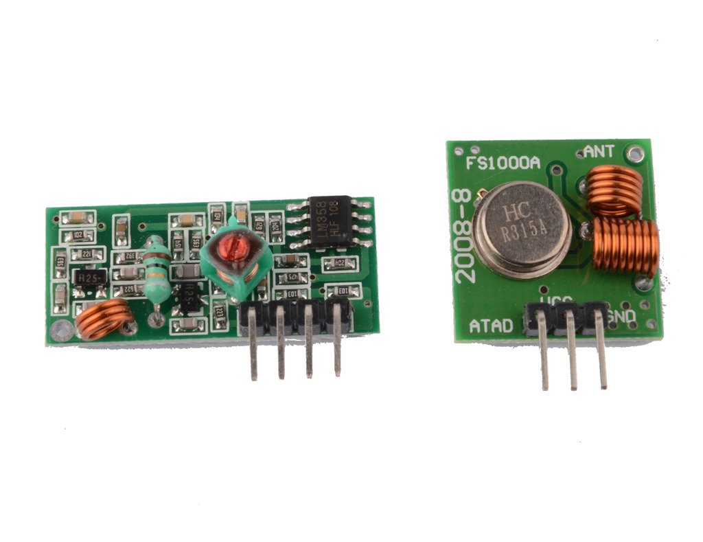
The receiver(left) and the transmitter(right) are small and cheap; I found the inexpensive radios in Aliexpress. The transmitter works in a range of 3V-12V with a current 20-28mA, and the receiver at 5.0V with static current of 4mA according to their specifications. Knowing that the ATTiny85 works in a voltage range of 2.7-5.5V, I imagined that this radios could work perfectly with ATTiny85.
The receiver radio has 4 pins which two of them are for data. They are located in the center; both of them share the same data, and they are interconnected. Meaning that it does not matter which pin I use, I will get the same data.
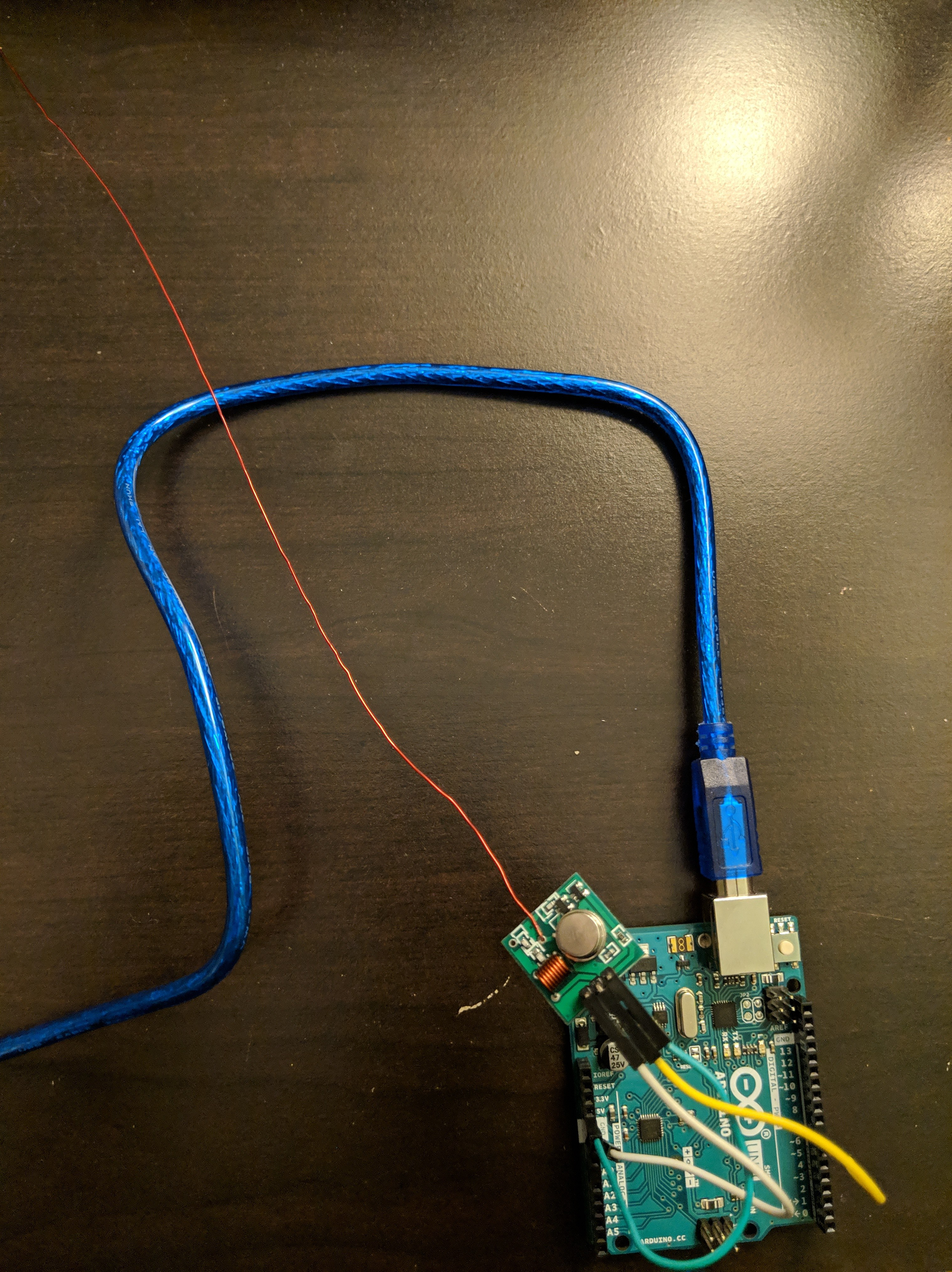
The transmitter configuration is very straightforward. Just one pin to transmit data; in the example code for the Arduino transmitter is the number 7 and 13 for a led. The only issue could be the antenna. I had to add a custom cable to the transmitter board to start receiving some data:
Software
For the communication process, I used the Manchester Encoding. The library for that is the Arduino Manchester Encoding which works perfectly with ATTiny85. I was thinking to use the RF24 library, but it almost uses all the ATTiny85 memory; so not adequate for this purpose.
Process
Another challenge was to modified the MagSpoof code: how to add the receiver code and handle the data to be treated as a new track without altering the MagSpoof original purpose. So I made a list of what I wanted with this project:
- Add wireless communication
- Have the same portability
- Easy to use
- Touch the code without altering its essence
- Implement the same button as code function trigger
I added a new function called receiveTrigger() which is in charge to receive the data, save it and run it after the new track arrived.
One of the main modifications was in the loop(). I added the functionality to keep track of the button status. If it is pressed for more than two seconds, it will run an infinite loop for the receiver function; which will keep track if it receives something or not. If it did not receive data during a period of time(7 seconds aprox), it will exit and go back to the main loop again.
Moreover, if the receiver starts capturing data, it will extended the time-out period of time to keep receiving all track until it detects the end of it which is the !(exclamation character). During this period of time, the led will blink every time it receives something(this increase the waiting period of time, but I added it for debugging purposes). After received the whole track, it will be the only one available to be used with MagSpoof. To make sure that only the new track will play, I run it as playTrack(2). With the 2 as parameter, I avoid the reverseTrack() function to be executed.
In order to do this, I changed some code in main process at the playTrack() function:
Original: for (int i = 0; tracks[track][i] != ‘\0’; i++)
Modified: for (int i = (!receivedSize) ? 0 : 1; (!receivedSize) ? tracks[track][i] != ‘\0’ : i < receivedSize; i++)
Also changing the tmp variable.
Original: tmp = tracks[track][i] – sublen[track];
Modified: tmp = ((receivedSize) ? buffer[i] : tracks[track][i]) – sublen[track];
With these changes, we are able to play our new track without altering the core of MagSpoof.
Testing
For PoC purposes, I used an Arduino Uno as transmitter implementing this example. The new code works great configuring an ATTiny85 with internal clock of 8MHz or 16MHz. The time to update a new track and blinking the led while updating was around 32 seconds with a baud rate of 1200, and it takes around 24 seconds with a baud rate of 2400. I recommend to comment-out the blink statement while receiving after a finished debugging process for more speed.
This thread explain the process of sending data from Arduino and receiving data in the MagSpoof:
Even when the transmission process takes a while to send a completed new track, you can add new functions to MagSpoof and run them when the MagSpoof received just a byte, for example. Be aware that the communication between Arduino and MagSpoof is not encrypted at all, just encoded.
Code: https://github.com/salmg/magspoof/tree/master/Utils/SDR
———————-
Update(03/08/2019): After fixing a few issues in the receiver code, the waiting time to receive a new track was reduced from 32 seconds to 10. The code is already updated.

Have fun!

Bro I could not see this new version on the electronics cat..anything like that soon?
LikeLike
Hello Frank.
I am not part of MagSpoof in Electronic Cats. You should email them directly or contact them by Twitter at https://twitter.com/electronicats
LikeLiked by 1 person